Hole-Making Tools | YCK2020
Xin giói thiệu các dụng cụ cắt gọt (Tools ) dùng trong phương pháp gia công lỗ (Hole-Making).
Đây cũng giúp ta có thêm cách Phân loại dụng cụ gia công lỗ, một phần quan trọng trong Công nghệ chế tạo máy.
Tags: Corner Radius Tool, Drill Cycles Speed Data,Taps, Hole-Making Tools, Cutting Feeds, Center-Spot Drills,
Center-Spot Drills
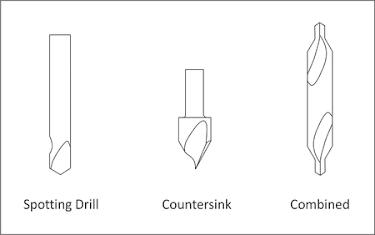
Center (spotting) drills
are short and very rigid drills used to create a conic on the face of the part.
Because they come to a sharp point and resist bending, they locate the hole
precisely. The conic helps prevent the subsequent drill from wobbling and
ensure the drill is located precisely and drills straight down.
Countersink drills are
used to create the conical face for a machine screw. Combined
spotting-countersinks are used to create a screw clearance hole and countersink
in one operation.
There are many different
sizes and tip angles of center, countersink, and combined drills. Be sure the
tip angle of the countersink matches the included angle of the machine screw,
and that the drill diameter is greater than the screw head diameter.
|
Figure
3.6: Countersink and Center Drill
|
Twist Drill
Twist drills are
available in many diameters and lengths. Usually made of high speed steel,
carbide, or cobalt, they may also be coated with titanium nitride (TiN) for
longer life. The tip angle of most twist drills is 118 degrees.
Taps
Cutting taps form
threads by shearing material away. Form taps (roll taps) form the thread by
forming the metal to shape. Form taps produce no chips and are used for soft
materials including aluminum, copper, brass and plastics.
Bottoming taps are used
to tap blind holes. Spiral point taps push the chip ahead and out the bottom of
a through hole.
Taps require a hole
drilled to the correct size to ensure the thread is formed properly. For
example, a ¼-20 cutting tap requires drilling a .201 (#7) hole. Refer to the
drill chart in Appendix F to find the correct drill size for
a specified thread size and fit.
Most CNC Machines
support rigid tapping, which means the tap can be held in a rigid holder. The
tap is advanced at a feed rate that matches the thread lead into the hole. The
spindle then stops, reverses, and backs out of the hole.
Machines without rigid
tapping require special tapping attachments. Always refer to the manufacturers'
instructions as the speed, feed, and other machining parameters for tapping
attachments may be different that those for rigid tapping.
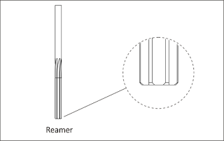
Use reamers to create
holes of precise shape and excellent surface finish. Reamed holes are usually
accurate within .0002 inches diameter. For example, a reamer is used for holes
used for ground pins and bushings.
Reamers require a
specific size hole be drilled before use. Cutting speeds and feeds are also
important. Remove too little or too much material and the hole will not be the
correct size.
Counterbore
A counterbore looks
similar to an end mill with a pilot in the center. It is used to spot face
holes and the pilot ensures the spot face is centered on the hole.
Counterboring is not
necessary when using a CNC machine. Rather, create a spot face using a pocket
or circle mill tool path. This saves having to buy and stock counterbore tools
and pilots, and the time required to load and set up the counterbore.
See more:
Bạn muốn tìm kiếm gì không?


